
Network Infrastructure: DNS, IP, DHCP, DHCP and DNS, NetBIOS, WINS, Name Resolution, OSI and DOD Models, Networking
The repair button in the Windows GUI:
All of the above can be done as discrete manual steps from the command line - and the Windows admin should know how to do each of these. Button is there for non-133t end losers and for speed.
Starting off on an aside: It sounds palatable to say, "AD and 2003/XP/2003 are IP and DNS based and NetBIOS stuff is just in there for convenience and backwards compatibility." Technically true, but not really accurate; and convenience has a huge scope in that statement:
The list is long. Try to run a Windows environment without NetBIOS and NBT...
NetBIOS resource browsing (enumeration?) can use a "null" session:
TCP/IP Addressing Relevant Terms:
IPv4 addresses are written as "dotted decimal" or in binary (BASE 2) as four octets, also dotted or separated by dots. Why an "octet"? It's like a string quartet (four) which has two violins, a viola, and a cello (or a quintet (five) or sextet (six)) an octet is eight bits working together.
Internet Protocol version 6 - IPv6
http://en.wikipedia.org/wiki/IPv6
Internet Protocol version 4 - IPv4
http://en.wikipedia.org/wiki/Ipv4
Subnet Addressing mini-tutorial - mostly focused on classfull networks
and networks vs. hosts
http://www.networkcomputing.com/unixworld/tutorial/001.html
Online IP Subnet Calculators
http://www.subnet-calculator.com
http://www.solarwinds.net/Tools/Free_tools/Subnet_Calc
http://www.wildpackets.com/products/free_utilities/ipsubnetcalc/overview
In Windows Server 2003, TCP/IP is installed by default and cannot be removed. Earlier versions of Windows allowed you to remove TCP/IP and reinstall it to return it to the installation defaults.
"netsh interface ip reset" When you run the reset command, it rewrites
pertinent registry keys that are used by the Internet Protocol (TCP/IP) stack
to reach the same result as the removal and the reinstallation of the protocol.
Reserved networks |
|
| 10 /8 | one private class A |
| 127 /8 | loopback is 127.0.0.1 |
| 169.254 /16 | APIPA |
| 172.16 /12 thru 172.31 /12 | 16 private class B’s |
| 192.168 /16 | 256 private class C’s |
Classfull IP ranges |
||
| class name/function | first octet in binary | first octet in decimal |
| Class A | 00xx xxxx | 1 to 126 |
| Class B | 10xx xxxx | 128 to 191 |
| Class C | 110x xxxx | 192 to 223 |
| multicast (Class D) | 1110 xxxx | 224 to 239 |
| experimental (Class E) | 1111 xxxx | 240 to 255 |
Subnet mask values in decimal and binary |
||||||||
| 2^7 | 2^6 | 2^5 | 2^4 | 2^3 | 2^2 | 2^1 | 2^0 | |
| 128 | 64 | 32 | 16 | 8 | 4 | 2 | 1 | |
Decimal |
Binary |
|||||||
| 0 | 0 | 0 | 0 | 0 | 0 | 0 | 0 | 0 |
| 128 | 1 | 0 | 0 | 0 | 0 | 0 | 0 | 0 |
| 192 | 1 | 1 | 0 | 0 | 0 | 0 | 0 | 0 |
| 224 | 1 | 1 | 1 | 0 | 0 | 0 | 0 | 0 |
| 240 | 1 | 1 | 1 | 1 | 0 | 0 | 0 | 0 |
| 248 | 1 | 1 | 1 | 1 | 1 | 0 | 0 | 0 |
| 252 | 1 | 1 | 1 | 1 | 1 | 1 | 0 | 0 |
| 254 | 1 | 1 | 1 | 1 | 1 | 1 | 1 | 0 |
| 255 | 1 | 1 | 1 | 1 | 1 | 1 | 1 | 1 |
One to X types of network traffic:
UNICAST - 1 to 1 - from one host's IP address to another host's IP address. Most network traffic is composed of unicast packets. A unicast packet is one that has been addressed to a single computer. The destination IP address in a unicast packet is a Class A, B, or C IP address that has been assigned to a single host.
BROADCAST - 1 to all - from one host's
IP address to all hosts IP address on the same network, via network's broadcast
address. When a packet is addressed to the IP address 255.255.255.255, this
is a local broadcast. A local broadcast is blocked by routers, but is propagated
by hubs and switches. Local broadcasts are used by many applications to announce
status and ensure that all interested hosts are informed of that status. A directed
broadcast is an IP address with all the host bits set to 1. Computers use directed
broadcasts to deliver a packet to all computers on a particular subnet. Broadcast
packets are inefficient because they are processed by all hosts on a subnet.
On a busy host/LAN, this may/will reduce performance levels.
MULTICAST - 1 to select many - from one
host's IP address to one or many or many many host's IP address. This functionality
is controlled by layer three router protocols where each multicast has host
subscribe and added and removed, and the data goes from router to router such
as to deliver the data to all applicable hosts. Can conceptualize as a unicast
that has a single source and branches off at routers to end up as multiple unicasts
from a single source, but more efficient than that.
Multicast packets are addressed to a group of computers using a Class D IP address.
All computers that are part of a multicast group use the same multicast address.
Any packets addressed to the multicast address are delivered to all computers
in the multicast group. When a computer joins a multicast group, it informs
the local router by sending an IGMP Join Group Request packet via multicast.
The router tracks which subnets it has multicast clients on and ensures that
multicast packets are forwarded to the proper subnets.
Multicast packets are an improvement compared with broadcast packets because
multicast packets are processed by all hosts up to only the Internet layer rather
than up to the Application layer. This reduces the processing load on busy hosts.
Routing is done at the IP layer (of the OSI / DOD / TCP models) and basically the point of that layer. At it's simplest level Network IDs are what determines the what's of IP routing. All the IPs, host IDs, subnet masks, CIDR*, VLSN*, supper-netting, broadcasts addresses all boil down to Network IDs.
A, or the, default gateway is generally a reference to a router on a network (AKA subnet)
The "gateway of last resort" is typically a entry in a routing table specifying what to do with an address the device has no other route for, often this is 0.0.0.0 and references an interface leading to the Internet.
A device's routing table is a what the OS user to direct or re-direct packets, either internally to itself, or to other networks via specific interfaces. The windows command route print shows the local routing table and is used to determine what stays on the box (loopback and local IPs) and what networks are found via each NIC - generally the local network (subnet) and everything else.
Microsoft NAT vs Cisco NAT/PAT:
Planning aspects of TCP/IP, device (hub, switch, router, etc.) placement:
The Well Known Ports are those from 0 through 1023.
The Registered Ports are those from 1024 through 49151
The Dynamic and/or Private Ports are those from 49152 through 65535
List of all IANA registered ports: http://www.iana.org/assignments/port-numbers
Another list of well known ports: http://insecure.org/nmap/data/nmap-services
Dynamic Host Configuration Protocol - DHCP
DHCP and DNS
For best results and correct exam answers, choose ADI-DDNS, Active Directory Integrated Dynamic DNS.
DNS Aging/Scavenging Simplified http://www.myitforum.com/articles/16/view.asp?id=6287 DHCP and DDNS and DNS scavenging and scavenging configuration hints
The DDNS (Dynamic DNS) client server relationship and roles - how the client updates DNS
Question: BIND supports DDNS, but with primary and secondary zones the clients
or DHCP servers can't update the secondary zones directly so what happens there?
Possible answer: Have DHCP do all the DDNS registration and point the DHCP server
at the primary zone for this only.
NetBIOS = Network Basic Input Output System. (IBM 1983)
Session layer protocol
NetBIOS is a flat namespace. All machines talking to one another must have unique names for everything to work smoothly. Using NBT, NetBIOS is routed over TCP/IP. Still NetBIOS ideally wants a flat name space, even over this routed space... The NetBIOS scope can be used to segregate NetBIOS namespaces.
NBT = NetBIOS over TCP/IP. Basically NetBIOS tunneled over IP
The NetBIOS Name suffix:
| Number(h) | Usage |
| 00 | Workstation Service |
| 20 | File Server Service |
| 1C | Domain Controllers |
Broadcast based NetBIOS name resolution
Windows Internet Naming Service - WINS
WiNS and lmhosts map NetBIOS to IP - in other words:
Resolves NetBIOS names to their IP and IPs to their NetBIOS names
Vastly preferable to NetBIOS broadcasts as WiNS uses unicast communications, name resolution crosses routers and network traffic is less
Automatic and dynamic - hosts register and remove themselves, WiNS grooms out dead records too
Microsoft's name for a NetBIOS Name Server, NBNS
Preferably all hosts will point to WiNS
WiNS servers need to point to themselves
I like to write it as WiNS, as it's an internet service, not an Internet one, but the the I is capitalized for the acronym I guess.
WiNS is sort of the evolved descendent of the lmhosts file
Client must be WINS compatible - to use WINS (non-Windows OSs can be WiNS clients, if designed as such)
Clients must be configured to use WINS (can be done by DHCP)
WINS offers no programmatic or GUI based delegation of administration
WINS is not easily segregated
The MAIN things WiNS does:
Multiple WiNS servers:
WiNS server configurations:
The WINS Proxy service:
This write up of WiNS is incomplete without also reading most of the Name Resolution section, below
See also the ARP section, below under networking - ARP is a basic primary underlying piece of name resolution
Winsock vs NetBIOS
| Winsock name to IP resolution sequence: | |
| Local resolution | |
| 1 | Hostname (I am trying to talk to myself?) |
| 2 | HOSTS file (Common malware target for exploit) (Actual static HOSTS file may not be parsed, but has already been read into the DNS client cache, so its content is used in the next step) |
| 3 | DNS cache (Client) All previous successful DNS resolutions (since startup or last cleared) are cached here |
| Network resolution: Primary | |
| 4 | DNS |
Network resolution: Secondary |
|
| 5 | NetBIOS cache |
| 6 | WINS (Assuming DNS suffixes and FQDNs line up) |
| 7 | NetBIOS broadcast |
| 8 | LMHOSTS file |
| NetBIOS name to IP resolution sequence: | |
| Local resolution | |
| 1 | Hostname (I am trying to talk to myself?) |
| 2 | NetBIOS cache |
| Network resolution: Primary | |
| 3 | WINS (H-node sequence - node types, below) |
| 4 | NetBIOS broadcast (H-node sequence - node types, below) |
| 5 | LMHOSTS file |
| Network resolution: Secondary Fail over to DNS name resolution (on the off chance; this is sort of a try everything or just in case of mis-configured clients.) |
|
| 6 | HOSTS file (see above in DNS name resolution sequence) |
| 7 | DNS cache (client) |
| 8 | DNS |
Node types |
||||
TYPE |
letter code |
hex code |
DESCRIPTION | Changes to NetBIOS name to IP resolution sequence above |
BROADCAST |
b-node |
1 |
Use broadcast only | Skips WINS, step 3 in NetBIOS name to IP resolution sequence above |
PEER TO PEER |
p-node |
2 |
Use WINS only | Skips NetBIOS broadcast, step 4 in NetBIOS name to IP resolution sequence above |
MIXED |
m-node |
4 |
Use broadcast first, then WINS | Switches WINS and NetBIOS broadcast, steps 3 and 4 in NetBIOS name to IP resolution sequence above |
HYBRED |
h-node |
8 |
Use WINS, then broadcast | No change to NetBIOS name to IP resolution sequence above |
NetBIOS node types are generally configured via DHCP's option 46. (Can use HKEY_LOCAL_MACHINE\SYSTEM\CurrentControlSet\Services\Netbt\Parameters\NodeType registry value to 1 (Microsoft-enhanced B-node), 2 (P-node), 4 (M-node), or 8 (H-node) to specify also.)
Some command line tools related to name resolution. See the COMMANDS to know section for more detail
HOSTS and lmhosts:
LMHOSTS
More than you probably want to know about NetBIOS over TCP/IP, from Chapter 11 of TCP/IP Fundamentals for Microsoft Windows of TechNet Home > Networking > Tasks > Evaluation & Planning. A few nice pix too.
Note that clients can be configured to point to multiple DNS servers. Logically if one DNS server is not available, DNS name resolution fails over to the next DNS server in the list. However Windows does NOT use a DNS service query to control this fail over (most *NIX systems do) so if the primary DNS server is up, for example, but the DNS service is not running on it, the client will not fail over to the secondary DNS server. Basically, if Windows can ping the server running said to be running DNS, that server is used. This complicates troubleshoot and maintenance.
OSI model |
Protocols / HARDWARE
at that layer |
TCP model | |||
| layer # | layer name | layer # | layer name | ||
| (9) | religion or money | ||||
| (8) | politics or power | ||||
| 7 | Application | HTTP, FTP, Telnet, SMTP, POP3, IMAP4, IDS, IPS, some FIREWALLS | 4 | Application | |
| 6 | Presentation | HARDWARE EN/DE-CRYPTION | |||
| 5 | Session | FULL/HALF DUPLEXING | |||
| 4 | Transport | TCP, UDP | 3 | Transport | |
| 3 | Network | IP, RIP, OSPF, ICMP, IGMP, ARP, ROUTERS, (VLAN routing SWITCHES) | 2 | Network (AKA Internet) | |
| 2 | Data Link | MAC | SWITCHES | ||
| LLC | |||||
| 1 | Physical | Ethernet (802.3), CSMA/CD, Token Ring, Wireless LAN (802.11b(etc.)), Bluetooth IEEE (802.15), WIRELESS, FIBER OPTIC, TWISTED-PAIR, HUBS, COAXIAL, REPEATERS | 1 | Host to Host (AKA Network) | |
The Windows 2000 TCP-IP network model.doc - The Windows 2000 TCP/IP network model MS Word formatted from a MS KB article
Mnemonic OSI devices: All People Seem To Need Data Processing (down the stack to send :-) Please Don't N T Sausage Pizza A (up the stack to receive :-)
----------------------------------------------------------------------------
The DoD (Department of Defense) (AKA TCP/IP model) model is a layered abstract description for communications and computer network protocol design. It was created in the 1970s by DARPA for use in developing the Internet's protocols, and the structure of the Internet is still closely reflected by the DoD model. It has fewer, less rigidly defined layers than the commonly referenced OSI model, and thus provides an easier fit for real-world protocols. It has four layers:
Layer 4 - Process Layer or Application Layer - This is where the "higher
level" protocols such as SMTP, FTP, SSH, HTTP, etc. operate.
Layer 3 - Host-To-Host (Transport) - This is where flow-control and connection
protocols exist, such as TCP. This layer deals with opening and maintaining
connections, ensuring that packets are in fact received.
Layer 2 - Internet or Internetworking Layer - This layer defines IP numbers,
with many routing schemes for navigating packets from one IP address to another.
Layer 1 - Network Access - This layer describes the physical equipment necessary
for communications, for example the MAC addresses of the network cards in an
Ethernet.
----------------------------------------------------------------------------
The Open Systems Interconnection Reference Model (OSI Model or OSI Reference Model for short) is a layered abstract description for communications and computer network protocol design, developed as part of the Open Systems Interconnection initiative. It is also called the OSI seven layer model.
Layer 1: Physical layer
The Physical layer defines all the electrical and physical specifications for
devices. This includes the layout of pins, voltages, and cable specifications.
Hubs, repeaters and network adapters are physical-layer devices. The major functions
and services performed by the physical layer are:
Layer 2: Data Link layer
The Data Link layer provides the functional and procedural means to transfer
data between network entities and to detect and possibly correct errors that
may occur in the Physical layer. The addressing scheme is physical which means
that the addresses (MAC address) are hard-coded into the network cards at the
time of manufacture. The addressing scheme is flat. Note: The best known example
of this is Ethernet. Other examples of data link protocols are HDLC and ADCCP
for point-to-point or packet-switched networks and Aloha for local area networks.
On IEEE 802 local area networks, and some non-IEEE 802 networks such as FDDI,
this layer may be split into a Media Access Control (MAC) layer and the IEEE
802.2 Logical Link Control (LLC) layer.
This is the layer at which bridges and switches operate. Connectivity is provided only among locally attached network nodes; however, there's a reasonable argument to be made that these really belong at "layer 2.5" rather than strictly at layer 2.
"Layer 2.5"
While not a part of the official OSI model, the term "Layer 2.5" has
been used to categorize some protocols that operate between layer 2 and layer
3. For example, Multiprotocol Label Switching (MPLS) operates on packets (layer
2) while working with IP addresses (layer 3) and uses labels to route packets
differently.
Layer 3: Network layer
The Network layer provides the functional and procedural means of transferring
variable length data sequences from a source to a destination via one or more
networks while maintaining the quality of service requested by the Transport
layer. The Network layer performs network routing, flow control, segmentation/desegmentation,
and error control functions. Routers operate at this layer -- sending data throughout
the extended network and making the Internet possible (there also exist layer
3 (or IP) switches). This is a logical addressing scheme - values are chosen
by the network engineer. The addressing scheme is hierarchical. The best known
example of a layer 3 protocol is the Internet Protocol (IP).
Layer 4: Transport layer
The Transport layer provides transparent transfer of data between end users,
thus relieving the upper layers from any concern with providing reliable and
cost-effective data transfer. The transport layer controls the reliability of
a given link. Some protocols are state and connection oriented. This means that
the transport layer can keep track of the packets and retransmit those that
fail. The best known example of a layer 4 protocol is TCP.
Layer 5: Session layer
The Session layer provides the mechanism for managing the dialogue between end-user
application processes. It provides for either duplex or half-duplex operation
and establishes checkpointing, adjournment, termination, and restart procedures.
The OSI model made this layer responsible for "graceful close" of
sessions, which is a property of TCP, and also for session checkpointing and
recovery, which is not usually used in the Internet protocol suite.
Layer 6: Presentation layer
The Presentation layer relieves the Application layer of concern regarding syntactical
differences in data representation within the end-user systems. MIME encoding,
data compression, encryption, and similar manipulation of the presentation of
data is done at this layer. Examples: converting an EBCDIC-coded text file to
an ASCII-coded file, or serializing objects and other data structures into and
out of XML.
Layer 7: Application layer
The Application layer services facilitate communication between software applications
and lower-layer network services so that the network can interpret an application's
request and, in turn, the application can interpret data sent from the network.
Through Application layer protocols, software applications negotiate their formatting,
procedural, security, synchronization, and other requirements with the network.
Some common Application layer protocols are HTTP, SMTP, FTP and Telnet.
Layer 8: Politics
This layer often overrides more technically astute decisions made at lower levels.
Needs at this level can dictate what happens below.
Layer 9: Religion or Money
This lay functions much like layer 8, but is more powerful. Religion can be
seen as non-logically based or rigid. Money is basically the ultimate decision
maker - it's all about dollars and sense.
----------------------------------------------------------------------------
en.wikipedia.org/wiki/OSI_model
en.wikipedia.org/wiki/DoD_model
www.cisco.com/univercd/cc/td/doc/product/iaabu/centri4/user/scf4ap1.htm
www.microsoft.com/technet/archive/winntas/maintain/featusability/tcparch.mspx
IEEE 802.3 = Ethernet.
Ethernet is de facto standard due to its high performance and low price.
Most common implementations use are 100 Mbps,1 Gbps, and 10 Mbps - highest speed
avail is 10 Gbps.
Diagram of an Ethernet frame (public domain from http://en.wikipedia.org/wiki/Image:Ethernet_frame.svg):
Ethernet Type II Frame ((public domain from http://en.wikipedia.org/wiki/Image:Ethernet_Type_II_Frame_format.svg):
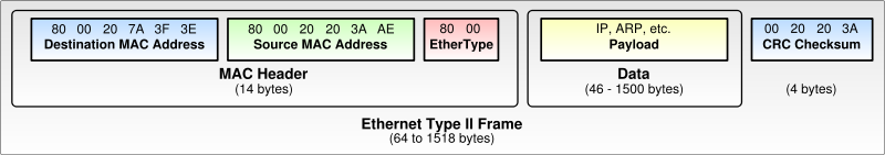
Both above images from the Ethernet page on Wikipedia
MAC address vs. IP address:
Internet vs. internet: Internet with a capital "I" is The Internet, the single global network of all networks; internet with a lower-case "i" is a network. This convention is often unknown, ignored, or mostly people simply don't refer to their network as an internet. (Note the breakdown, however, of CIDR, WINS, and ICND (Cisco class name))
ARP - Address Resolution Protocol
Network Driver Interface Specification
- NDIS
http://en.wikipedia.org/wiki/NDIS
NDIS is a specification created by Microsoft and 3Com to speed the development
of device drivers and enhance networking capabilities. NDIS acts as an intermediary
for all communication between the protocol and the network card driver. When
a protocol is configured to use an adapter, it is referred to as a binding.
Bindings between protocols and adapters are controlled by NDIS. A single adapter
can be bound to multiple protocols. A single protocol can also be bound to multiple
adapters. This is very important in a computer that is acting as a router or
a server that communicates with clients using multiple protocols.
2003 uses v5.1, supports v4
Transport Driver Interface - TDI
The TDI layer provides clients and services with access to network resources.
Applications talk to the TDI layer and the TDI layer passes on the requests
to the protocols. TDI emulates two network access mechanisms: Network Basic
Input/Output System (NetBIOS) and Windows Sockets (WinSock). Network Basic Input/Output
System (NetBIOS) is an older network interface that is used by Windows 9x and
Windows NT to access network resources. Windows Sockets (WinSock) is used by
Internet applications such as Internet Explorer and Outlook Express to access
network resources. Starting with Windows 2000, WinSock can also be used by Windows
to access Active Directory-based resources. Windows Sockets Direct (WinSock
Direct) is a new enhancement to WinSock that is used to access resources on
system area networks.
Developers write services and clients that communicate with NetBIOS or WinSock
to access network resources. The applications communicate with the TDI layer,
which emulates these interfaces. Developers creating protocols code them to
communicate with the TDI layer. For a client and service to communicate, they
must both be using the same network access mechanism and protocol.
Description
of Auto-static and Periodic Update Modes
http://support.microsoft.com/Default.aspx?kbid=241545
The operation mode of an interface determines whether the interface is treated
as a 24 hours a day, 7 days a week (24x7) connection, such as a network adapter,
or if the interface is treated like a DOD (Dial On Demand) connection, which
is not normally a 24x7 connection. Periodic update mode means that RIP broadcasts
or multicasts are sent over this interface based on the periodic rate, with
a default value of once every 30 seconds. The Auto-static update mode indicates
that periodic updates are not sent over the interface and that manual updates
by the administrator are necessary. You may notice that by default, network
adapters use periodic update mode, and DOD connections use Auto-static update
mode. The administrator may change the update mode as necessary.
Client |
Service |
Transport Driver Interface (TDI) |
|
TCP/IP |
IPX/SPX |
Network Driver Interface Specification
(NDIS) |
|
NIC Driver
|
|